By Victor Rao MBBS, DMRD, RDMS
Introduction
Anisotropy is a commonly encountered ultrasound imaging artifact when performing musculoskeletal ultrasound (MSKUS). It is important to be able to anticipate and recognize this artifact and adjust transducer angulation in real time to make sure it is indeed an anisotropy artifact and not a real pathology. It could be easily mistaken for a pathological finding or could even hide a pathological finding in the hypoechoic region created by this artifact.
Anisotropy results in anatomical structures such as ligaments, tendons, nerves and some muscles appearing hypoechoic (dark) when the ultrasound beam does not strike the tissue plane at a perpendicular angle. This artifact can be explained by the law of ultrasound physics.
This artifact is created due to the reflection properties of structures like tendons and ligaments. Even a slight deviation of a few degrees from perpendicular can cause significant changes in the ultrasound image, sometimes mimicking tendinopathy or tears (hypoechoic).
Law of Reflection
The Law of Reflection states that the angle of incidence is equal to angle of reflection. When an ultrasound beam is perpendicular (90°) to the tendon fibers, you get a strong reflection of the ultrasound beam back to the ultrasound transducer. This results in a hyperechoic image of the structure such as a tendon.
If the angle of incidence of the ultrasound beam originating from the transducer is not perpendicular to the tendon fibers, then following the law of reflection, the reflected ultrasound beam is not reflected to the transducer. It gets worse as the angle of incidence increases or deviates further from 90 degrees. See Figure 2. This results in the structure appearing darker or hypoechoic. The problem with this is that when the tendon is inflamed and there is fluid collection in that region, it tends to appear hypoechoic on ultrasound. So, the user may get confused and may interpret the anisotropy artifact as an actual lesion (false positive diagnosis).
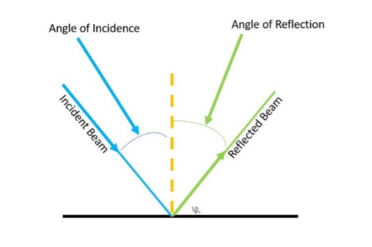
Figure 1. Diagrammatic representation of the Law of Reflection which states that the angle of incidence is equal to angle of reflection. For a reflected ultrasound beam to reach the transducer footprint strongly, the angle of incidence should be close to zero or the incident ultrasound beam should hit the region of interest at 90 degrees or very close to 90 degrees.
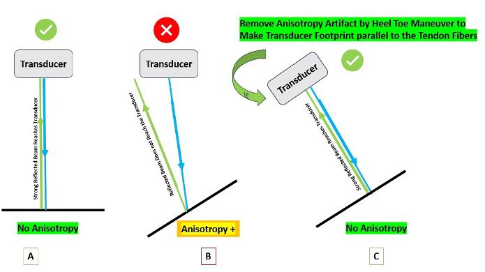
Figure 2. A – No anisotropy created because the tendon fibers are perpendicular to the ultrasound beam. B-Tendon fibers are not perpendicular to the ultrasound beam, so the reflected ultrasound beam does not reach the transducer resulting in anisotropy. C- Heel-Toe maneuver performed to make the ultrasound beam perpendicular to the tendon fibers to eliminate anisotropy artifact.
Mechanism and Appearance of Ultrasound Images
- Collagen-rich structures such as tendons and ligaments have highly organized fibers that reflect ultrasound waves strongly when they are perpendicular to the ultrasound beam. This makes the normal tendon appear bright and normal on an ultrasound image.
- If the angle of incidence is more than 5 degrees, then the reflected ultrasound beam does not reach the transducer from that region making the tendon appear hypoechoic. The resulting hypoechoic region can be misinterpreted as a pathological lesion (e.g., tendon tear), especially when imaging curved or angled anatomical structures.
- Anisotropy can also make the needle poorly visible during an ultrasound-guided procedure if the ultrasound beam is not perpendicular to the needle resulting in a loss of reflected ultrasound waves returning to the transducer.
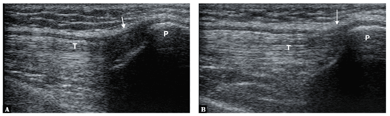
Figure 3. Anisotropy artifact in the image on the left (A) seen in the region of insertion of the quadriceps femoris tendon (T). Image on the left (B) shows reduced anisotropy artifact simply by adjusting the angulation of the transducer footprint relative to the quadriceps femoris tendon and slight flexion at the knee. Image courtesy of Małgorzata Serafin-Król et al. See reference article in the references section.
Let us look at some examples below of actual lesions which should not be confused with anisotropy artifact. Tendon tears, rupture or tendinopathy may appear like anisotropy. Transducer angulation or maneuvers such as heel-toe maneuver will not change the appearance of the lesion. Observe how they appear very similar to the anisotropy artifact.
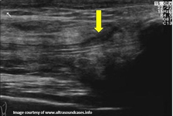
Figure 4. B-mode image showing rupture of superficial part of the quadriceps tendon. This was not an anisotropy artifact. The hypoechoic lesion did not disappear by changing the angulation of the transducer to make the ultrasound beam perpendicular to the tendon fibers. Always correlate clinically and compare with the normal side.
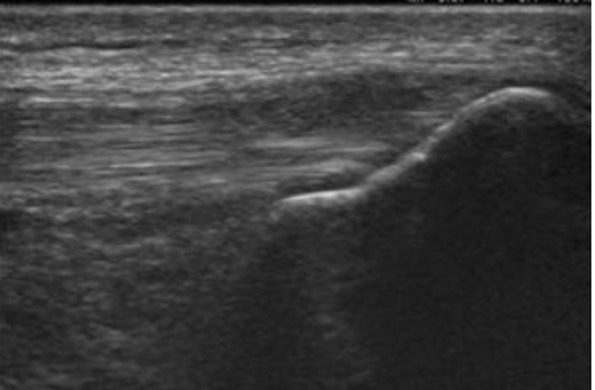
Figure 5. B-mode longitudinal image showing hypoechoic quadriceps tendon tendinopathy. The hypoechoic areas did not disappear even by proper angulation of the transducer to eliminate potential anisotropy artifact. Image courtesy of www.ultrasoundcases.info
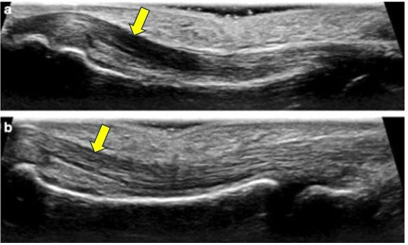
Figure 6. The top image (a) shows anisotropy artifact in the flexor tendon of the 3rd finger. The hypoechoic anisotropy artifact in the image was corrected in the lower image (b) by changing the angulation of the transducer to make the ultrasound beam hit the tendon at 90 degrees. This results in homogeneous echogenicity of the tendon. Image courtesy of ResearchGate.net. Be aware that if it was a true lesion such as tendinitis or tendon tear, heel-toe maneuver or other corrective techniques will not remove the hypoechoic region in the image.
Importance of Anisotropy in Clinical Practice
Understanding anisotropy is essential for accurate MSK ultrasound diagnosis:
- Prevents false positive findings (do not make a false positive diagnosis by misidentifying anisotropy artifact as tendon pathology or nerve injury).
- Enables clinicians to distinguish true tissue abnormalities from artifacts by tilting or angling the transducer, using maneuvers such as ‘heel-toe’ or fanning.
Techniques to Minimize Anisotropy
- Always attempt to keep the ultrasound beam perpendicular to the structure of interest.
- Use heel-toe or fanning maneuvers to dynamically adjust the angle of incidence, when anisotropy artifact is encountered.
- Undergo rigorous hands-on training to identify and learn to remove the anisotropy artifact.
Conclusion
Anisotropy artifact occurs when tendons or ligaments lose echogenicity due to oblique insonation of the incident ultrasound beam, mimicking pathology. Tendons and ligaments are most affected. Advanced transducers with beam steering or crossbeam imaging can help reduce anisotropy. To confirm anisotropy, hold the transducer at 90°. If the hypoechoic area disappears, it was anisotropy; if it persists, it is a true lesion. Clinicians must ensure accurate interpretation to avoid misdiagnosis. Always document and save images with and without anisotropy.
References
- Diagnostic errors in musculoskeletal ultrasound imaging and how to avoid them https://jultrason.pl/assets/pdf/artykuly/jou-2017-0028.pdf
- An Illustrated Tutorial of Musculoskeletal Sonography: Part I, Introduction and General Principles – https://doi.org/10.2214/ajr.175.3.1750637
- Musculoskeletal Ultrasound Artifacts – https://radiologykey.com/musculoskeletal-ultrasound-artifacts/
- Artifacts in Musculoskeletal Ultrasonography: From Physics to Clinics – https://doi.org/10.3390/diagnostics10090645
- Artifacts in Musculoskeletal Ultrasonography – https://www.thieme-connect.com/products/ejournals/pdf/10.1055/s-0034-1365830.pdf
- https://www.youtube.com/watch?v=avNjJ5V0Ks8&list=PL3zW0pI5xTOShKWkQAkuvv2WN9m4dxp1A (Watch YouTube short video)
Access the full POCUS Learning Library for FREE!
Share a few details so we can tailor new content to your specialty and region.